Motivation
For a while I wanted to design my own h-bridge circuit for driving higher power motors for some robots. There are lots of solutions on the market for hobby robots ( such as popular L298 ) but it seems there is some gap ( or at least I don’t know any IC in reasonable package in price) for driving motors 4-8 A. Quite often the popular drivers have some drawbacks (L298 is based on BJT’s, it gets quite hot when driving with 1 A ), other popular motor drivers ( like the cytron one ) are rated for 30V 10A which is not really my interest (they also cost quite a bit compared to spare components and some basic PCB).
One of other goals was to learn how to do this circuit properly, so later maybe it will be integrated in one PCB with some robot controller ( and have everything on one board). Also I thought it might be cool and valuable experience how to make that circuit work well.
Goal
My goal was to design a driver that would be able to drive medium power ( aiming for 30-100 W motor ) driver efficiently. At the time I was doing the driver, I was working on the ROV ( Remotely Operated Vehicle for underwater environments) and one of the concerns we had there was generating heat ( so I wanted to really minimize the amount of wasted energy). Having said that, and starting to look into how it’s done it looks pretty easy : first thing that will pop out will be some H-bridge circuit, just 4 mosfets connected ( most likely 2 P-Channel, 2 N-channel), some information about how to drive them with PWM signals and that’s all. Looks pretty easy. Although when I started to experiment it turned out that designing good driver is not that easy, and involves quite a bit of tricks ( might be inexperience or lack of knowledge at the point of writing ). Here are some notes, that might be useful when designing custom DC motor driver.
Specification
- Dimensions : as small as possible PCB, relying on SMD components to achieve low-cost and small dimensions. I’m aiming for 2-channel driver with 8cm x 4cm ( Tops 10cm x 5cm ) and price going as low as possible ( but still achieving ok results ).
- Rating : should perform well when driving few Amp loads ( I didn’t want to go past tops 80W per channel with 12V battery so my maximum should be approximately 7-8 A ( some extra, just to be safe) ). I don’t suspect passing this setup ( 12V, few Amps) anytime soon, but I wanted to do my driver properly so I might as well pick some components that can handle higher ratings ( 24V and tens of amps in future ? not sure )
- Typical interface with ENable pins and PWM pins ( 2 enables and 2 Signals per motor)
- Should be able to measure roughly the current passing through the motor. Shouldn’t be super precise but have decent performance
- backEMF also implemented on board
Design
More or less my thought/research process of tacking the problem :
Simulation in circuit.js
Fig 1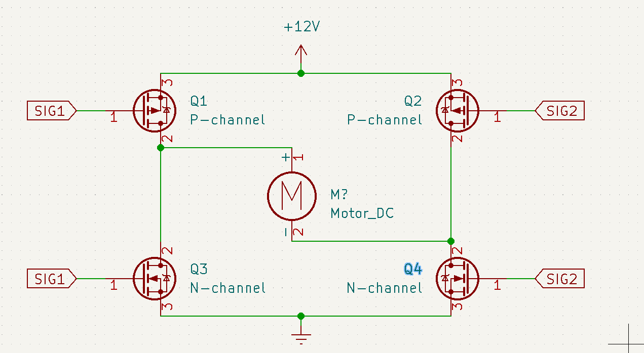
The above (Fig 1) is super typical image of the h-bridge driver, and illustrates the idea of driving a motor. If the SIG1 is On and SIG2 is Off then Q1 is non-conducting, Q2 is conducting, Q3 is conducting, and Q4 is non conducting (therefore Current goes through +12V -> Q2 -> Motor -> Q3 -> Ground). if SIG1 is Off and SIG2 is ON then Q1 is conducting, Q2 is non-conducting, Q3 is conducting and Q4 is non-conducting ( therefore Current goes through +12V -> Q1 -> Motor -> Q4 -> Ground).
My first thought that because the pairs Q1, Q3 are Q2 and Q4 you can connect both of the SIG1 (so they are the same signal) and all be good. That is not necesarily the case. The Mosfets, by design have some capacitance, therefore it takes time to charge/discharge the mosfet. It’s also important to remember the plots for mosfets.
So let’s say we would do that : let’s turn the Q1 and Q3 to High. Q1 is off ( non conducting ) and Q3 is on (conducting). What happens when we change the signal to Low ? Well the voltage on the gates because of the capacitance will change, but it will change from high to low in some time. As the discharging goes ( so the process of High -> Low), the Q1 becomes more conductive and Q3 becomes less. But there is a point where Q1 will beconductive and Q3 will be conductive. That causes huge problem : We have a short (VCC -> Q1 ( low resistance )-> Q3 (low resistance) -> GND). It’s called a “Shot-through” and can cause serious damage. Mitigation of that is to use dedicated driver, or some special options in Microcontrollers. [1]Less problematic, although still a concern for power efficiency is the P-Channel / N-Channel pair. P-Channel mosfets have much more resistance then N-channels (also they cost typically more)
So up to this point I know more or less what we need : we need an effective mosfet driver (that will avoid the problems from point 1. ) and we most likely need 4 N-channel mosfets (Lower $R_{DS-ON}$ and cheaper). We operate wil lower voltages so mosfets will definitely do (compared to IGBT [2]). Picking the most appropriate might be a bit tricky ; main concern when picking would be :
- current limits ( those typically won’t be a problem, most likely tens of amps),
- $R_{DS-ON}$ (not a huge problem, even old technology mosfets have it less then 10mohms, currently it’s even lower ),
- voltage limits (not a problem, we don’t have any high/low voltages, rather typical 12-30 V)
- switching time ( which requires some thought): gate resistance effects both turn-on and turn off times (it’s like a resistor connected in series to the capacitor ). This introduces a tradeoff between losses (problem from 1. ) and dv/dt of drain to source : the faster the transition the lower the power losses ( make sense, it limits the problem from 1. as much as possible ). But ithe faster transition makes more ringing and introduces more EMI
When picking the mosfet driver, it’s crucial to look into gate charge (in [2] it’s pointed out why use gate charge not gate capacitance).
Some other features would be nice to add, such as current measurement or back emf for measuring rotation ? They look easy to implement, not sure how usefull data we would actually get
Realization
- Mosfet driver : NCP5901
Looks pretty good, also mentioned in elektor article [1]. Supports driving 2 N-Channel mosfets. It needs a separate power supply when going more then 12V ( max is 13.2V). Available for 0.1£ in RS components ! - Mosfets : STP150N3LLH6 or IRLR8726 : Both are available in DPAK and are pin to pin replacements. Both are cheap and Are more then enough for the what it looks like any motor I’m gonna use ever. Both have very good Rds (2.4 mOhm and 5.8 mOhm), and total gate charge (40nC, 15nC respectively) which should be OK I guess.
- BackEMF : realized with 4 resistors
- Current measurement : Realized with one very low value resistor and op amp
Currently V1 schematic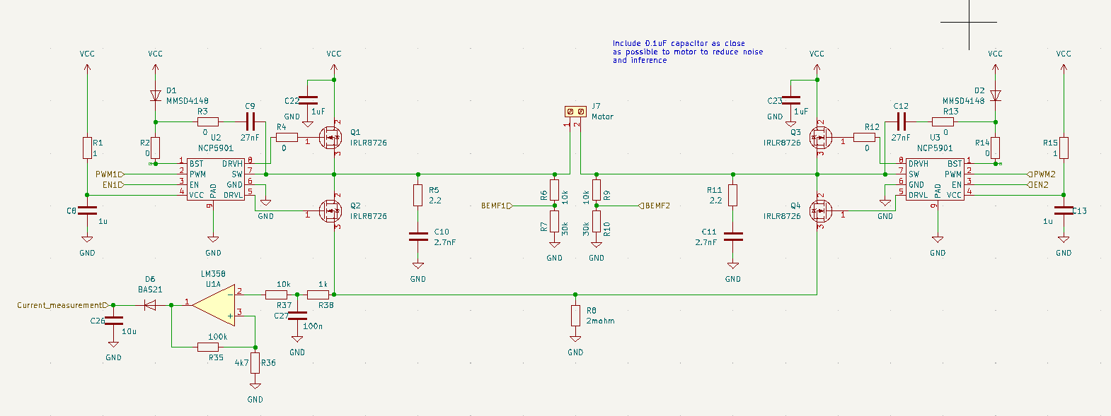
Layout
Current Renders of the layout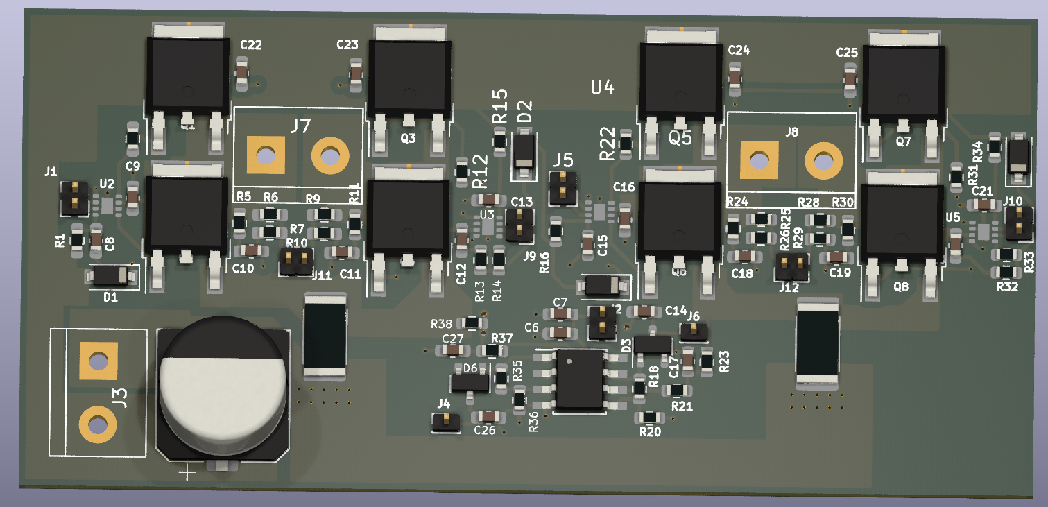
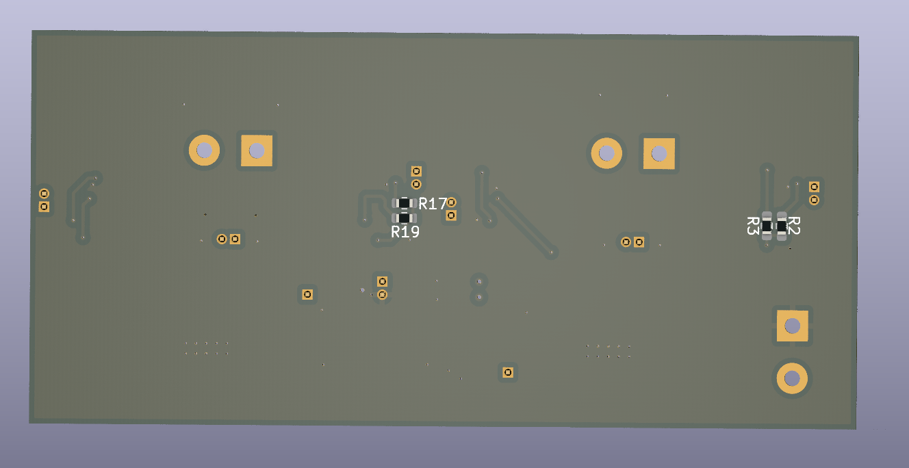
The PCB is 2 layers. On top there are only signal layers and few ground planes for high current paths. Bottom is a huge ground plane, and there are only few traces there ( which I wasn’t been able to route on top). Almost all ( except for some jumpers ) components are on front. I tried to minimilize the lengths of traces that charge/discharge mosfets ( the mosfet drivers ones). The mosfets and sensitive components ( like drivers and decoupling capacitors were put first). The mosfets are placed really close to each other, simillar as in [3].
References
- Elektor Magazine January & February 2022 [1]
- AN898 : Determining MOSFET Driver Needs for Motor Drive Applications [2]
- Best Practices for Board Layout of Motor Drivers [3]